Most fiber installations fail during planning, not execution. I've watched crews rip out perfectly good cable pulls because someone missed a critical measurement or ignored environmental factors. The difference between a weekend project and a month-long nightmare? Understanding what you're doing before the first cable reel shows up.
This breakdown covers everything—the boring paperwork that saves you later, the physical work that makes your back hurt, and the testing that proves you did it right. Skip sections at your own risk.
Planning Your Fiber Cable Installation Project
Pull out a notepad before touching any cable. I mean physically walk every inch of where this fiber needs to go. Take photos. Measure twice. Write down the weird stuff—that tight corner near the loading dock, the mystery conduit that supposedly goes to Building C, the ceiling tile that someone painted over the access panel.
Site surveys aren't exciting, but they're where money gets saved. Check if existing pathways actually work. That 2-inch conduit from 1987? Might be full of abandoned coax. Run a test rope through before ordering 5,000 feet of fiber. Finding a collapsed section after delivery means expensive delays and awkward conversations with your boss.
Calculate distances with a 15% buffer minimum. Cables don't run in straight lines—they go up, down, around obstacles, with service loops at both ends. Measure the actual path, not the "as the crow flies" distance some architect drew on a plan.
Permits depend on where you're working and who owns what. Municipal right-of-way projects? Expect paperwork. Lots of it. Utility companies want 30-45 days notice for pole attachments. Underground work requires calling 811 for locates—do this even on private property unless you enjoy explaining to angry building owners why their internet died. Traffic control permits for street crossings take another 2-3 weeks in most cities.
Safety planning means more than buying hard hats. Who's qualified for aerial work? Does everyone understand lockout/tagout for electrical rooms? Have you coordinated with the building manager about temporarily disabling security systems? The fiber you're about to pull might share conduit with active circuits—cutting the wrong cable turns a routine job into a crisis.
Your checklist before starting: cable arriving on the right date (not two weeks early to sit in the weather), tools calibrated within the last year, splice closures matching the environment (don't use indoor-rated enclosures outside), and every crew member briefed on the sequence. Document what's already there with photos. Trust me on this—you'll want proof when someone claims you damaged something that was already broken.
Author: Rachel Denholm;
Source: milkandchocolate.net
Essential Tools and Equipment for Fiber Installation
Manual pullers work fine for 200-foot building runs. Anything longer? You want powered equipment. A good capstan winch with tension monitoring costs $3,000-$8,000 but prevents the single most expensive installation mistake—pulling too hard. That needle creeping past 600 pounds? Stop immediately. Fiber cores can stretch without the jacket showing damage, and you won't discover the problem until testing reveals mysterious high loss.
Budget for a fusion splicer if you're doing more than basic patch cable connections. Quality units start around $8,000 (used) and top out past $35,000 for models that handle specialty applications. Modern splicers align cores automatically and estimate loss before you've even removed the fiber from the holders. A good splicer pays for itself in time savings if you're joining more than a couple hundred fibers per year. Mechanical splices cost less per termination ($15-$30 versus $1-$2 for fusion) but produce higher loss—0.3-0.5 dB compared to 0.05-0.1 dB.
OTDRs separate professional installers from amateurs. These instruments document everything—splice locations, loss at each connection, the exact distance to any problem. Single-mode work requires dual-wavelength testing (1310nm and 1550nm). Expect to spend $8,000-$25,000 for a capable unit. Some installers rent them at $200-$400 per week, which makes sense for occasional projects.
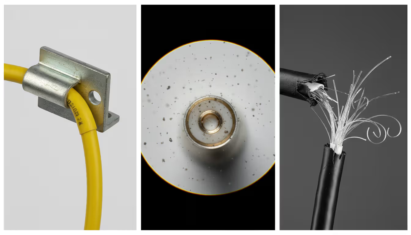
Here's what nobody tells you about cleaning: it matters more than expensive equipment. A $30,000 splicer can't fix dirty fiber. Stock 99% isopropyl alcohol (the 70% stuff from drugstores leaves residue), lint-free wipes (not paper towels), and canned air designed for fiber optics. A basic USB inspection microscope costs $300-$600 and reveals contamination invisible otherwise. One dust particle smaller than you can see causes 1 dB loss or complete failure.
Cut-resistant gloves aren't optional. Glass fiber slivers penetrate skin easily and migrate under the surface, requiring minor surgery to remove. Ask me how I know. Safety glasses protect against fiber fragments during cleaving and stripping. Hard hats, high-vis vests, and proper footwear complete the basics.
Testing equipment rounds out your kit: visual fault locators ($100-$300) for quick checks, power meters and light sources ($400-$1,200 for a quality set), and cable ID tools for working near active fibers you absolutely cannot disrupt.
Step-by-Step Fiber Cable Installation Process
Preparing Cable Pathways and Conduits
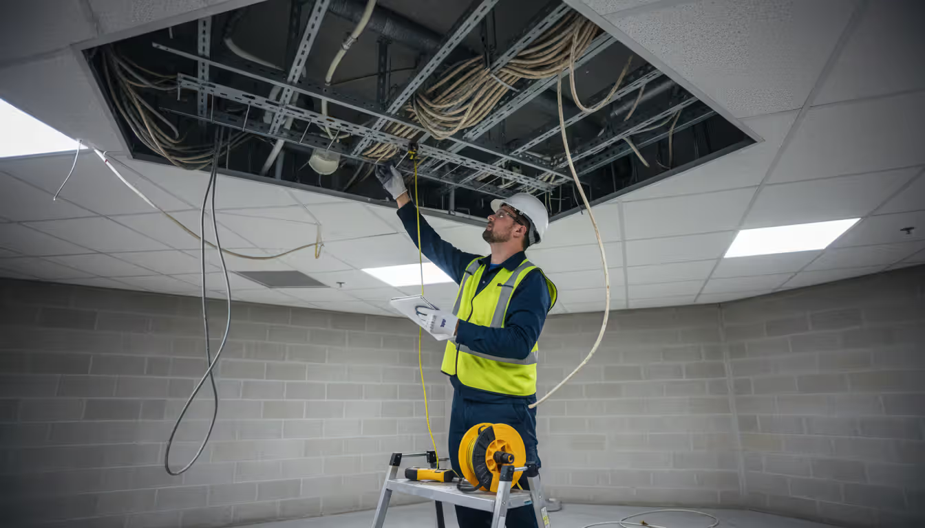
Clean everything first. Seriously. That conduit you're about to use has been accumulating crud since it was installed. Pull a brush through, swab out standing water, remove debris. Check every access point for sharp edges—a protruding bolt or rough concrete lip destroys cable jackets during pulls. Pad sharp corners with foam or purpose-made corner protectors.
Install pull rope using fish tape for short distances (under 100 feet) or compressed air blowers for long runs. Secure pulling grips properly—a failure mid-pull through 800 feet of conduit means starting completely over. For innerduct installations, verify the math: cable shouldn't fill more than 60% of the cross-section. Jam it tighter and you're asking for installation problems and future headaches.
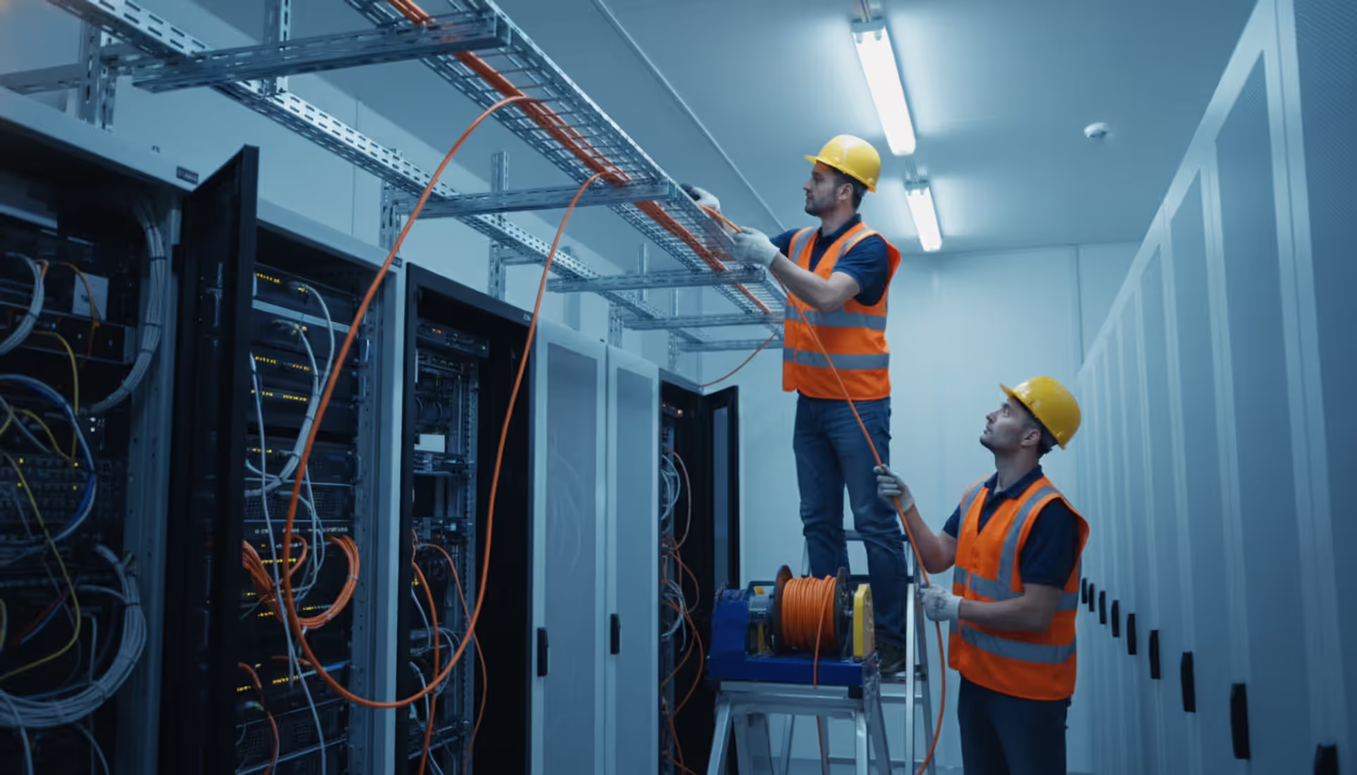
Cable tray calculations matter more than most people think. A 6912-fiber cable weighs substantially more than equivalent copper—add multiple fiber runs and you might exceed tray load ratings. Space cables so you can identify and access individual runs later. Bunching everything together looks neat initially but makes troubleshooting miserable.
Pulling and Routing Fiber Cable
Gather everyone for a pre-pull meeting. Establish hand signals because shouting over 400 feet doesn't work. Define maximum pulling speed (usually walking pace) and abort conditions. Station someone at the reel to watch for snags, an operator at the puller to monitor tension and speed, and spotters at intermediate points to guide cable and watch for problems.
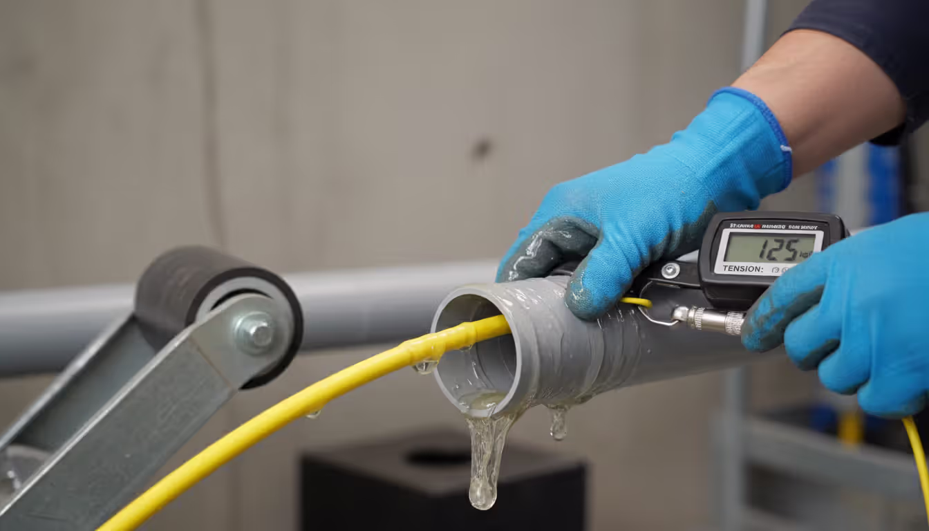
Lubrication isn't optional for conduit pulls. Use fiber-approved lubricant generously—pour it into the conduit entrance and apply directly to cable as it enters. The wrong lubricant degrades cable jackets. The right stuff costs $30-$50 per gallon and reduces friction dramatically.
Watch that tension gauge obsessively. Most outside plant cables max out at 600 pounds pulling tension, though specifications vary. Exceeding limits even briefly creates stress points that fail later—sometimes months later after you've left and someone else gets blamed.
Bend radius rules exist for good reasons. During installation under tension: 20 times the cable diameter minimum. Once installed and secured: 10 times diameter. A 0.9-inch cable needs an 18-inch radius during pulling, 9 inches after installation. Use corner rollers at turns. Never force cable around tight spaces—if it resists, the pathway needs modification.
Aerial installations require different thinking. Lashing machines provide consistent support spacing (12-18 inches typical). Self-supporting cables with integrated messenger strands need proper tension calculations—too tight stresses attachment points, too loose creates wind load issues and excessive sag.
Author: Rachel Denholm;
Source: milkandchocolate.net
Securing and Protecting Installed Cable
Support horizontal runs every 4-5 feet using J-hooks or cable tray support. Vertical runs need closer spacing—every 3 feet prevents cable weight from creating stress at lower sections. Don't overtighten supports. Compression damage doesn't always show immediately but causes problems later.
Protect vulnerable points aggressively. Floor crossings need burial below slab or heavy-duty surface protection rated for expected traffic (not just "something to cover it"). Wall penetrations require fire-rated sealing to maintain building fire separation. This isn't optional—it's code.
Label both ends, plus intermediate access points. Include circuit ID, fiber count, cable type, installation date. Use weather-resistant labels outdoors. Maintain separate documentation with detailed pathway information, splice locations, and test results. Future you (or your replacement) will appreciate the effort.
Service loops at termination points and splice locations: 10-15 feet provides adequate slack for future work without creating tangled messes. Secure loops with velcro straps, not zip ties. Velcro allows adjustment without cutting; zip ties compress cable if overtightened (and someone always overtightens them).
Fiber Cable Termination Methods and Best Practices
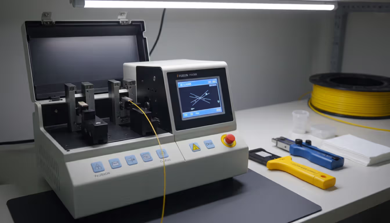
Fusion splicing permanently joins fibers by melting them together. The process starts with cleaving—creating perfectly flat end faces using a precision cleaver that scores and breaks the fiber. Cleave quality determines splice quality. A bad cleave with an angled end face produces high-loss splices regardless of splicer quality.
Strip coating from the fiber and clean with alcohol and lint-free wipes. Position fibers in the splicer, which uses cameras to detect core position within a micron. The splice cycle takes 10-30 seconds—an electric arc melts the fibers together. Quality splicers display estimated loss immediately based on core alignment.
Protect completed splices with heat-shrink protectors providing mechanical strength and environmental sealing. Organize splices in trays within enclosures, maintaining bend radius and keeping individual fibers identifiable. Well-organized splice enclosures allow future technicians to add or modify connections without disturbing existing work.
Mechanical splicing relies on alignment fixtures with index-matching gel to join fibers—no heat, no expensive equipment. These field-installable connectors work well for temporary connections or repairs when fusion equipment isn't available. The trade-off: higher loss values (typically 0.3-0.5 dB versus 0.05-0.1 dB).
Connector installation offers two main approaches: pre-terminated assemblies with factory-installed connectors (lowest loss, highest reliability, requires precise length measurements) or field termination using epoxy-and-polish or mechanical connectors (more flexibility when exact lengths aren't known).
Polishing technique separates acceptable from excellent connectors. Use figure-eight motions on polishing film, progressing from coarse to fine grit. Light pressure only—excessive force creates convex end faces that increase loss. Inspect every connector under magnification before installation. Properly polished connectors show smooth, scratch-free surfaces with the fiber core visible as a small circle centered in the ferrule.
Quality standards: maximum insertion loss typically 0.5 dB for single-mode connectors, 0.75 dB for multimode. Return loss measures light reflected back—higher values (more negative numbers) indicate better connections. Single-mode connections should achieve -50 dB or better.
Author: Rachel Denholm;
Source: milkandchocolate.net
Understanding Fiber Cable Types and Construction
Single-mode fiber uses a small core (8-10 microns) allowing only one light mode. This design enables transmission beyond 40 kilometers without amplification and supports higher bandwidths than multimode. Single-mode dominates telecommunications and campus backbones. The catch: equipment costs more than multimode equivalents.
Multimode fiber features larger cores (50 or 62.5 microns) accepting multiple light modes simultaneously. This design works with less expensive LED light sources and forgives alignment tolerances. However, modal dispersion limits distance to 300-550 meters for 10 Gigabit applications. Multimode serves data centers, building risers, and applications where distance limitations don't matter.
Loose tube construction houses fibers in gel-filled or dry buffer tubes within the cable jacket. Individual fibers move slightly within tubes, isolating them from stresses caused by temperature changes or installation tension. This design dominates outside plant applications where temperature swings occur. Standard loose tube cables contain 6-12 fibers per tube, with multiple tubes wrapped around a central strength member.
Tight buffer construction applies a 900-micron plastic coating directly to each fiber for crush resistance and easier handling. These cables work well indoors where environmental protection matters less. Tight buffer designs simplify termination—individual fibers are already protected and route directly to connectors.
Armored cables incorporate steel or fiberglass reinforcement against rodents and crushing. Burial applications in areas with rocky soil or active rodent populations justify additional cost. Some designs use corrugated steel tape; others employ interlocking steel wire for maximum protection.
Strand counts range from simplex single-fiber cables to extreme high-density designs. A 6912-fiber cable represents massive density, typically using ribbon technology where 12 or 24 fibers arrange in flat ribbons for mass splicing simultaneously. These ultra-high-count cables serve data centers and metropolitan networks where space is limited but fiber requirements are enormous. Installing 6912-fiber cable requires specialized equipment and expertise—cable diameter approaches 2 inches, and weight demands powered pulling equipment for any significant distance.
Fiber Cable Color Coding Standards
The industry uses a standardized twelve-color sequence for fiber identification: blue, orange, green, brown, slate, white, red, black, yellow, violet, rose, aqua. This pattern repeats for higher fiber counts, with subsequent groups distinguished by tracer stripes or different tube colors.
Buffer tubes use their own color sequence matching the same twelve-color pattern. A technician referencing "orange tube, green fiber" immediately identifies fiber position 15 in standard cable layouts.
Connector boots and patch cords use color to indicate fiber type: yellow identifies single-mode, orange or aqua indicates multimode (aqua specifically denotes OM3 or OM4 laser-optimized multimode). This visual distinction prevents accidentally connecting incompatible equipment.
Polarity matters in duplex and multi-fiber connections. Standards define A-to-B connectivity where position 1 at one end connects to position 12 at the other for 12-fiber MPO connectors. Colored boots and cable jackets help maintain correct polarity through complex installations.
Common Installation Mistakes and How to Avoid Them
Author: Rachel Denholm;
Source: milkandchocolate.net
Bend radius violations cause immediate or delayed failures. Installers rushing to complete pulls sometimes force cables around tight corners, creating micro-bends that increase attenuation or break individual fibers. Damage might not appear in initial testing if fractures are incomplete, only to cause failures months later when temperature changes or vibration complete the break. Use corner rollers, plan pathways with adequate space for curves, never force resistant cables.
Contamination accounts for a significant percentage of connection problems. A fingerprint on a connector end face, dust in a splice enclosure, or gel from loose tube cables on connector ferrules all cause high loss or complete failure. Establish clean work areas for termination, use dust caps religiously, inspect every connection before mating. Seconds spent cleaning properly prevent hours troubleshooting.
Excessive pulling tension damages fiber cores without visible external signs. Pulling too hard stretches glass, creating stress points that fail prematurely. Exceeding maximum tension even briefly can reduce cable lifespan by years. Use pulling eyes or grips distributing force across cable strength members, never pull on jacket alone, monitor tension continuously during installation.
Documentation errors create maintenance nightmares. Unlabeled splice points, missing as-built drawings, or incorrect fiber identification waste hours during troubleshooting or expansion projects. Document as you go rather than relying on memory after installation completes. Photograph splice trays, record OTDR traces for every fiber, maintain both digital and physical copies.
Ignoring environmental requirements causes predictable failures. Installing indoor-rated cable outdoors exposes it to UV degradation and moisture infiltration. Using non-plenum cable in air-handling spaces violates fire codes. Failing to seal conduit entrances allows water accumulation that freezes in winter, crushing cables. Match cable specifications to actual environment, not idealized conditions.
Testing and Troubleshooting After Installation
The difference between adequate and excellent fiber installation comes down to discipline.Anyone can pull cable and make connections that pass initial testing. But installations delivering reliable service for decades follow strict protocols at every step—proper tension monitoring, meticulous cleaning procedures, thorough documentation. Cutting corners might save an hour during installation but costs days troubleshooting years later
— Michael Torres
Continuity testing verifies basic connectivity using a visual fault locator (VFL). These red laser sources inject visible light into one fiber end—if light appears at the far end, the fiber is continuous. VFLs also help identify specific fibers in bundles and can locate breaks in cables up to 5 kilometers away by spotting light leaking from damaged sections.
Insertion loss measurement quantifies total loss from end to end using a light source and power meter. Set reference by connecting the light source directly to the power meter through a short test cable, then insert the installed fiber into the test setup. The difference between reference and installed readings gives total loss. Compare results against loss budgets calculated from cable length, connector count, and splice count. Single-mode links typically budget 0.5 dB per connector, 0.1 dB per splice, and 0.35 dB/km for cable attenuation.
OTDR testing provides detailed fiber characterization by sending short light pulses and analyzing backscattered reflections. The resulting trace shows distance to each event (connectors, splices, bends, breaks) and quantifies loss at each point. Bidirectional OTDR testing—measuring from both ends—gives most accurate results by averaging out measurement artifacts.
Analyze OTDR traces for anomalies: high-loss splices indicating poor fusion quality, reflective events suggesting dirty connectors or poor polishing, unexpected loss increases indicating cable damage. Save traces as baseline documentation for future comparison—rising loss values over time indicate developing problems.
Establish acceptance criteria before testing begins. Typical specifications require maximum end-to-end loss (often 1.5-3.0 dB depending on link length), minimum return loss (-40 dB for multimode, -50 dB for single-mode), and maximum loss per splice (0.1-0.3 dB). Individual splice losses exceeding 0.5 dB warrant investigation and possible re-termination.
Troubleshooting high-loss connections starts with cleaning and re-testing. If loss persists, inspect connector end faces under magnification for scratches, pits, or contamination. For splices, review fusion splicer data—high estimated loss during splicing indicates a problem that won't improve. Re-cleave and re-splice fibers showing excessive loss.
Comparison of Fiber Cable Types
Cable Type
Core Size
Maximum Distance
Bandwidth
Typical Applications
Installation Complexity
Single-mode
8-10 μm
40+ km without amplification (100+ km with quality optics)
Essentially unlimited for current applications (handles 100+ Gbps easily)
What is the minimum bend radius for fiber cable installation?
During installation under tension, maintain at least 20 times the cable's outer diameter as bend radius. Once installed and secured, this reduces to 10 times diameter. For example, a cable with 1-inch diameter needs at least 20 inches radius while pulling, dropping to 10 inches after permanent installation. Violating these limits causes attenuation increases or fiber breakage. Always verify manufacturer specifications—some specialty cables have stricter requirements.
How long does fiber cable installation typically take?
Duration varies dramatically based on project scope. A straightforward point-to-point connection between two buildings might take 4-8 hours including termination and testing. Complex installations with multiple splice points, difficult pathways, or high fiber counts can require days or weeks. Budget roughly 100-150 feet per hour for conduit pulls, 2-3 minutes per fusion splice, and 30-60 minutes per fiber for testing depending on link length and complexity.
Can I install fiber cable myself or do I need a professional?
Straightforward indoor installations using pre-terminated cables are manageable for experienced network technicians with proper training. However, splicing, OTDR testing, and outside plant installations demand specialized skills and expensive equipment. Consider professional installation for projects involving fusion splicing, cables exceeding 12 fibers, outdoor environments, or situations where network downtime is unacceptable. Professional installation costs often prove less than repairing amateur mistakes.
What's the difference between indoor and outdoor fiber cable installation?
Outdoor cables feature UV-resistant jackets, moisture barriers, and often include armoring for rodent protection. They're engineered for temperature extremes and direct burial or aerial installation. Indoor cables prioritize fire safety with plenum or riser ratings but lack environmental protection. Never use indoor cable outdoors—UV exposure degrades jackets within months. Outdoor cable can function indoors in some situations but may not meet fire code requirements for plenum spaces.
How do you terminate fiber cable ends?
Termination approaches include fusion splicing to pre-terminated pigtails, field-installing connectors using epoxy-and-polish techniques, or using mechanical field-install connectors. Fusion splicing produces lowest loss but requires expensive equipment. Epoxy connectors need careful polishing and take 10-15 minutes per connector. Mechanical connectors install quickly but typically show higher loss values. Choose based on performance requirements, budget, and available equipment.
What causes fiber cable installation failures?
Common failure causes include excessive pulling tension stressing fiber cores, bend radius violations creating micro-bends or breaks, contamination on connectors or splice points, moisture intrusion through unsealed enclosures, and improper cable selection for the environment. Many failures don't appear immediately—stressed fibers might pass initial testing but fail months later. Following manufacturer specifications, maintaining cleanliness, and thorough testing prevent most problems.
Successful fiber cable installation balances technical precision with practical project management. The investment in proper planning, quality tools, and thorough testing pays dividends through decades of reliable network operation. Whether you're installing a single cable or a 6912-fiber backbone, the principles remain consistent: respect minimum bend radius, maintain cleanliness, monitor pulling tension, and document everything.
The fiber installation landscape continues evolving with higher-density cables, improved connector technologies, and more sophisticated test equipment. Yet the fundamentals haven't changed—careful preparation, attention to detail during installation, and comprehensive testing remain hallmarks of quality work. Approach each project methodically, never rush critical steps like splicing or testing, and build a reputation for installations that perform flawlessly from day one through decades of service.
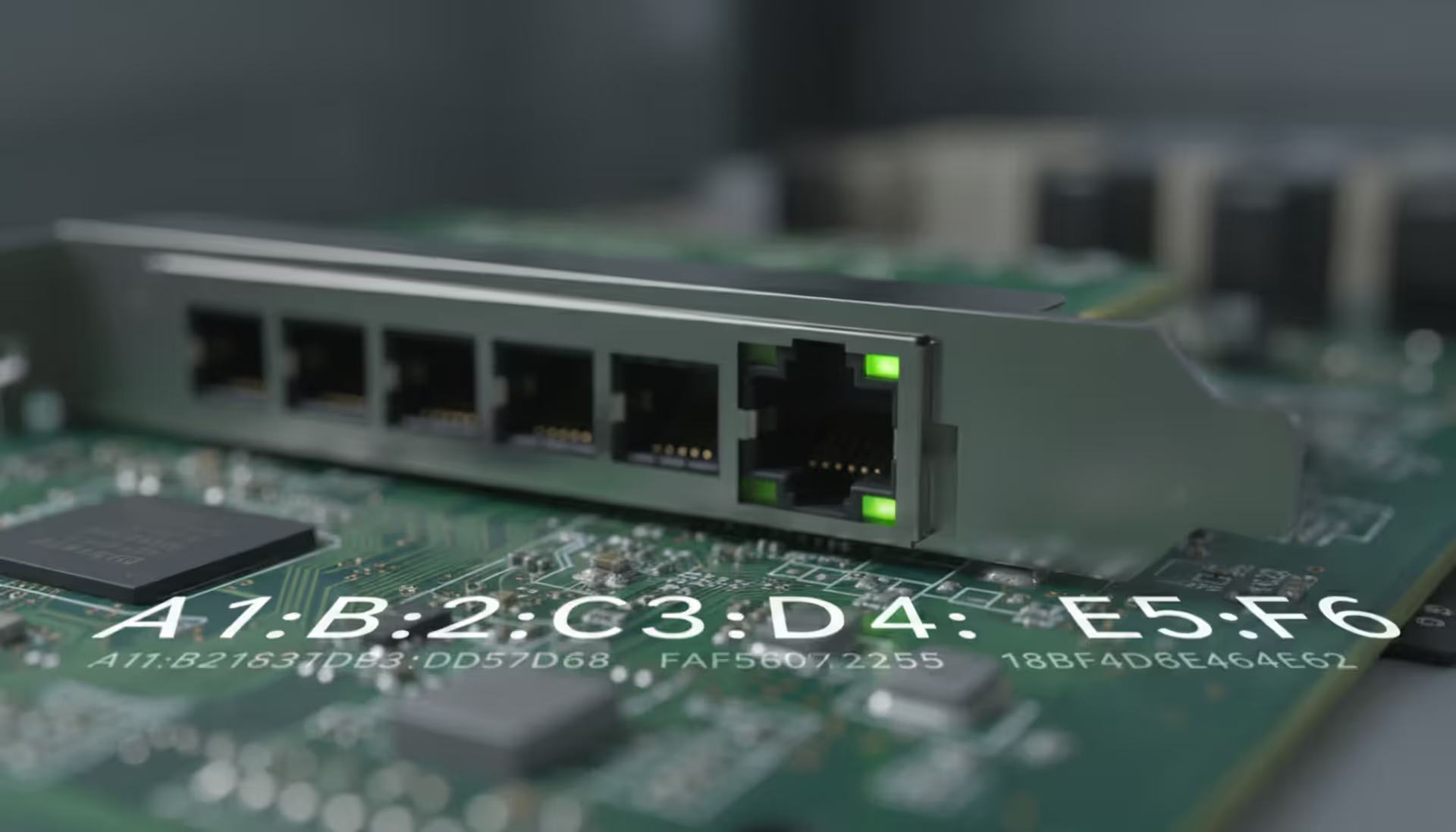
Every network device carries a unique MAC address identifier. This guide shows you how to find MAC addresses using command-line tools, system settings, and vendor lookup databases. Includes step-by-step instructions for Windows Command Prompt, macOS, Linux, and mobile devices
Migrating to the cloud doesn't always require reimagining your entire infrastructure. Lift and shift migration moves applications to the cloud with minimal modifications—a pragmatic approach for organizations facing data center deadlines or managing legacy systems
Network failures don't announce themselves politely. For small and medium businesses, disruptions translate directly into lost revenue and damaged reputation. This guide explains IT network support services, when you need professional help, and how to choose between in-house teams and managed providers
Building your own cloud storage gives you complete control over your data while potentially saving money compared to subscription services. This comprehensive guide covers hardware requirements, software platforms like Nextcloud, step-by-step installation, security best practices, and common mistakes to avoid
The content on this website is provided for general informational purposes only. It is intended to offer insights, commentary, and analysis on cloud computing, network infrastructure, cybersecurity, and IT solutions, and should not be considered professional, technical, or legal advice.
All information, articles, and materials presented on this website are for general informational purposes only. Technologies, standards, and best practices may vary depending on specific environments and may change over time. The application of any technical concepts depends on individual systems, configurations, and requirements.
This website is not responsible for any errors or omissions in the content, or for any actions taken based on the information provided. Users are encouraged to seek qualified professional advice tailored to their specific IT infrastructure, security, and business needs before making decisions.